


Vince Sanders
April 26, 2013
Share this post:


Reading time:
Collabora recently had a problem with a project's ARM build farm. In a nice change of pace it was not that the kernel was crashing, nor indeed any of the software or hardware.
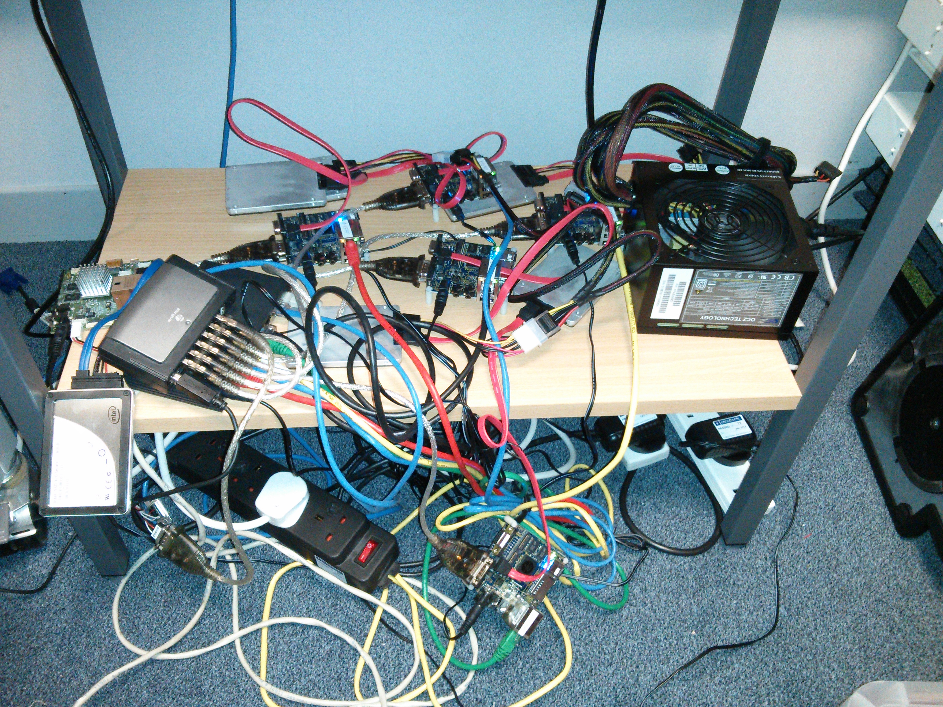
Instead our problem was our build farm could best be described as "a pile of stuff" and we wanted to add more systems to it and have switched power control for automated testing.
Which is kinda where the Christopher Alexander quote comes into this. I suggested that I might be able to come up with a better, or at least cleaner, solution.

19 inch subracks for mounting circuits inside submodules.
I originally envisaged the dev boards individually mounted inside these boxes. However preliminary investigation revealed that the enclosures were both expensive and used a lot of space which would greatly increase the rack space required to house these systems.

I decided to instead look at eurocard type subracks with carriers for the systems. Using my 3D printer I came up with a carrier design for the imx53 QSB and printed it. I used the basic eurocard size of 100mm x 160mm which would allow the cards to be used within a 3U subrack.
Once assembled it became apparent that each carrier would be able to share resources like power supply, ethernet port and serial console via USB just as the existing setup did and that these would need to be housed within the subrack.

The carrier prototype was enough to get enough interest to allow me to move on to the next phase of the project. I purchased a Schroff 24563-194 subrack kit and three packs of guide rails from Farnell and assembled it.
Initially I had envisaged acquiring additional horizontal rails from Schroff which would enable constructing an area suitable for mounting the shared components behind the card area.

Unfortunately Schroff have no suitable horizontal profiles in their catalog and are another of those companies who seem to not want to actually sell products to end users but rather deal with wholesalers who do not have their entire product range!

Undaunted by this I created my own horizontal rail profile and 3D printed some lengths. The profile is designed to allow a 3mm thick rear cover sheet attached with M2.5 mounting bolts and fit rack sides in the same way the other profiles do.
At this point I should introduce some information on how these subracks are dimensioned. A standard 19 inch rack (as defined in IEC 60297) has a width of 17.75 inches(450.85mm) between the vertical posts. The height is measured in U (1.75 inches)
A subrack must obviously fit in the horizontal gap while providing as much internal space as possible. A subrack is generally either 3 or 6 U high. The width within a subrack is defined in units called HP (Horizontal Pitch) which are 0.2 inches(5.08 mm) and subracks like the Schroff generally list 84 usable HP.
However we must be careful (or actually just learn from me stuffing this up ;-) as the usable HP is not the same thing as the actual length of the horizontal rails! The enclosures actually leave and additional 0.1 inch at either end giving a total internal width of 85HP (17 inches, 431.8 mm) which leaves 0.75 inches for the subrack sides and some clearance.
The Schroff subrack allows eurocards to be slotted into rails where the card centre line is on HP boundaries, hence we describe the width of a card in the slot in terms of HP

I cannot manufacture aluminium extrusions (I know it is a personal failing) nor produce more than 100 mm long length of the plastic profile on my printer.
Even if full lengths are purchased from a commercial service (120 euros for a pair including tax and shipping) the plastic does not have sufficient mechanical strength.
The solution I came up with was somewhat innovative, as an alternative a M5 bolt into a thread in the aluminium extrusion I used a 444mm long length of 4mm threaded rod with nuts at either end. This arrangement puts the extrusion under compression and gives it a great deal of additional mechanical strength as the steel threaded rod is very strong.

Additionally to avoid having to print enough extrusion for the entire length I used some 6mm aluminium tube as a spacer between 6HP(30.48mm) wide sections of the printed extrusion.
It was intended to use a standard modular PC power supply which is 150mm wide which is pretty close to 30HP (6 inches) so it was decided to have a 6HP section of rail at that point to allow a rear mounting plate for the PSU to be attached.
This gives 6HP of profile, 21HP(106.68mm) of tube spacer, 6HP of profile, 46HP(233.68 mm) of tube spacer and a final 6HP profile summing to our total of 85HP. Of course this would be unnecessary if a full continuous 85HP rail had been purchased, but 6 of 6 HP long profile is only 51 euro a saving of 70 euro.
To provide a flat area on which to mount the power switching, Ethernet switch and USB hubs I ordered a 170 x 431 mm sheet of 3mm thick aluminium from inspiredsteel who, while being an ebay company, were fast, cheap and the cutting was accurate.
Do be sure to mention you would prefer it if any error made the sheet smaller rather than larger or it might not fit, for me though they were accurate to the tenth of a mm! If you would prefer the rear section of the rack to be enclosed when you are finished, buy a second sheet for the top. For my prototype I only purchased a 170 x 280mm sheet as I was unsure if I wanted a surface under the PSU (you do, buy the longer sheet)

Mounting the PSU was a simple case of constructing a 3 mm thick plate with the correct cutouts and mounting holes for an ATX supply. Although the images show the PSU mounted on the left hand side of the rack this was later reversed to improve cable management.
The subrack needed to provide Ethernet switch ports to all the systems. ATP-Link TL-SF1016DS 16-Port 10/100Mbps Switch was acquired and the switch board removed from its enclosure. The switch selected has an easily removed board and is powered by a single 3.3V input which is readily available from the ATX PSU.
Attention now returned to the eurocard carriers for the systems, the boards to be housed were iMX53 QSB and iMX6 SABRE Lite and a Raspberry Pi control system to act as USB serial console etc.
The carriers for both main boards needed to be 8HP wide, comprised of:
Although only 38 mm this is 7.5HP and fractions of an HP are not possible with the selected subrack.
With 8HP wide modules this would allow for ten slots, within the 84 usable HP, and an eleventh 4HP wide in which the Raspberry Pi system fits.

Carrier designs for both the i.MX53 QSB and the i.MX6 SABRE Lite boards were created and fabricated at a professional 3D print shop which gave a high quality finish product and removed the perceived risk of relying on a personal 3D printer for a quantity of parts.
This resulted in changes in the design to remove as much material as possible as commercial 3D services charge by the cubic cm. This Design For Manufacture (DFM) step removed almost 50% from the price of the initial design.

The i.MX6 design underwent a second iteration to allow for the heatsink to be mounted and not mechanically interfere with the hard drive (although the prototype carrier has been used successfully for a system that does not require a hard drive). The lesson learned here is to be aware that an design iteration or two is likely and that it is not without cost.
The initial installation was to have six i.MX53 and two i.MX6 this later changed to a five/four split, however the carrier solution allows for almost any combination, the only caveat (discovered later) is the imx53 carriers should be to the right hand side with the small 4HP gap at that end as they have a JTAG connector underneath the board which otherwise foul the hard drive of the next carrier.

A wiring loom was constructed for each board giving them a connector tail long enough to allow them to be removed. This was the wrong approach! if you implement this design (or when I do it again) the connector tails on the wiring loom should present all the connections to the rear at the same depth as the Ethernet connection.
The rack cables themselves should be long enough to allow the slides to be removed but importantly it is not desirable to have the trailing cable on the cards. I guess the original eurocard designers figured this out as they designed the cards around the standard fixed DIN connectors at the back of the card slots.

We will now briefly examine a misjudgement that caused the initially deployed solution to be reimplemented. As the design was going to use USB serial converters to access the serial console a USB connected relay board was selected to switch the power to each slot. I had previously used serial controlled relay boards with a USB serial convertor however these were no longer available.

All the available USB relay boards were HID controlled, this did not initially seem to be an issue and Linux software was written to provide a reasonable interface. However it soon became apparent that the firmware on the purchased board was very buggy and crashed the host computer's USB stack multiple times.
Once it became apparent that the USB controlled power board was not viable a new design was conceived. As the Ethernet switch had ports availableEthernet controlled relay boards were acquired.

It did prove necessary to design and print some PCB support posts with M3 nut traps to allow the relay boards to be easily mounted using double sided adhesive pads.

By stacking the relay boards face to face and the Ethernet switch on top separated using nylon spacers it was possible to reduce the cable clutter and provide adequate cable routing space.
A busbar for Ground (black) and unswitched 12V (yellow) was constructed from two lengths of 5A chock block.
An issue with power supply stability was noted so a load resistor was added to the 12V supply and an adhesive thermal pad used to attach it to the aluminium base plate.

It was most fortunate that the ethernet switch mounting holes lined up very well with the relay board mounting holes allowing for a neat stack.
This second edition is the one currently in use, it has proved reliable in operation and has been successfully updated with additional carriers.
The outstanding issues are mainly centered around the Raspberry Pi control board:
The final bill of materials (excluding labour and workshop costs) which might be useful to anyone hoping to build their own version.
Prices are in GBP currency converted where appropriate and include tax at 20% and delivery to Cambridge UK and were correct as of April 2013.
The purchasing was not optimised and for example around 20GBP could be saved just by ordering all the shapeways parts in one order.
| Base subrack | |||
|---|---|---|---|
| Item | Supplier | Quantity | Line Price |
| Schroff 24563-194 subrack kit | Farnell | 1 | 41.28 |
| Schroff 24560-351 guide rails | Farnell | 3 | 13.65 |
| Schroff rack rear horizontal rail | Shapeways | 2 | 100.00 |
| 1000mm length of 4mm threaded rod | B and Q | 1 | 1.48 |
| 170mm x 431mm x 3mm Aluminium sheet | inspired steel | 2 | 40.00 |
| PSU mounting plate | Shapeways | 1 | 35.42 |
| PCB standoff | Shapeways | 4 | 22.30 |
| 160mm Deep Modular PC supply | CCL | 1 | 55.76 |
| TP-Link TL-SF1016DS 16-Port 10/100Mbps-Switch | CCL | 1 | 23.77 |
| 8 Channel 16A Relay Board Controlled Via Ethernet | Rapid | 2 | 126.00 |
| Raspberry Pi | Farnell | 1 | 26.48 |
| USB Serial converters | CCL | 10 | 37.40 |
| 10 port strip style USB HUB | Ebay | 1 | 7.00 |
| Parts for custom Ethernet cables | RS | 13 | 26.00 |
| Parts for custom molex power cables (salvaged from scrap ATX PSU) | Workshop | 11 | 11.00 |
| 33R 10W wirewound resistor for dummy load | RS | 1 | 1.26 |
| 24pin ATX female connector pre-wired | Maplin | 1 | 2.99 |
| Akasa double sided thermal pad | Maplin | 1 | 5.00 |
| Small cable tie bases | Maplin | 1 | 6.49 |
| Miscellaneous cable, connectors, nylon standoffs, solder, heatshrink, zip ties, nuts, washers etc. | Workshop | 1 | 20.00 |
| Total for subrack | 603.28 | ||
The carriers are similarly not optimally priced as over five GBP each can be saved by combining shipping on orders alone. Also the SSD drive selection was made some time ago and a newer model may be more suitable.
| i.MX53 QSB carrier | |||
|---|---|---|---|
| Item | Supplier | Quantity | Line Price |
| i.MX53 QSB | Farnell | 1 | 105.52 |
| Intel 320 SSD 80G | CCL | 1 | 111.83 |
| Carrier board | Shapeways | 1 | 30.00 |
| combined sata data and power (15 to 20cm version) | EBay | 1 | 5.00 |
| Low profile right angle 5.5mm x 2.1mm barrel jack | EBay | 1 | 0.25 |
| Parts for 9pin serial cable extension | RS | 1 | 5.00 |
| Miscellaneous solder, heatshrink, nylon nuts, bolts and washers | Workshop | 1 | 5.00 |
| Total for carrier | 262.60 | ||
| i.MX6 SABRE Lite carrier | |||
|---|---|---|---|
| Item | Supplier | Quantity | Line Price |
| i.MX6 SABRE Lite | Farnell | 1 | 128.06 |
| Intel 320 SSD 80G | CCL | 1 | 111.83 |
| Carrier board | Shapeways | 1 | 35.00 |
| combined sata data and power (15 to 20cm version) | EBay | 1 | 5.00 |
| Low profile right angle 5.5mm x 2.1mm barrel jack | EBay | 1 | 0.25 |
| Parts for 9pin serial cable modification | RS | 1 | 2.00 |
| Miscellaneous solder, heatshrink, nylon nuts, bolts and washers | Workshop | 1 | 5.00 |
| Total for carrier | 287.14 | ||
The solution works and in a 3U high 355mm deep subrack ten ARM development boards can be racked complete with local ethernet switching, power control and serial consoles.

The solution is neat and provides flexibility, density and reproducibility the "pile of stuff" solution failed to do.
For current prototype with nine filled slots the total cost was around 3000GBP or around 330GBP per slot which indicates a 100GBP per slot overhead over the "pile of stuff" solution. These figures omit the costs of the engineer and workshop time, which are estimated at an additional 1500GBP. Therefore a completed rack, fully filled with i.MX6 carriers costs around 5000GBP
Density could be increased if boards with lower height requirements were used however above twelve units there issues with Ethernet switch, power switch and USB port availability become a factor. For Example the 16 port Ethernet switch requires a port for uplink, one for each relay board and one for the console server which leaves only 12 ports for systems.
Addressing the outstanding issues would result in a much more user friendly solution. As the existing unit is in full time use and downtime is not easily scheduled for all ten systems, the issues are not likely to be fixed on the prototype and would have to be solved on a new build.
The solution is probably not suitable for turning into a product but that was not really the original aim. A commercial ARM blade server using this format would almost certainly use standard DIN connectors and a custom PCB design rather than adapting existing boards.
07/07/2026
AI development is shifting from implementing models from scratch to composing powerful capabilities via APIs, enabling developers to integrate…
26/05/2026
New upstream BlueZ documentation helps simplify Bluetooth qualification for Linux-based products by mapping supported profiles, test requirements,…
14/05/2026
See how Tyr moves beyond MCU firmware boot to build the group, queue, VM, submission, and completion paths needed to run real Vulkan workloads…
07/05/2026
A complete breakdown of Mesa’s NIR compiler detailing how it optimizes shader memory access with SSA promotion, deref analysis, copy propagation,…
05/05/2026
Collabora brought Bluetooth Auracast broadcasting to MediaTek Genio 700 for Embedded World 2026. Here's the complete, fully Open Source…
22/04/2026
Using our XR expertise, Collabora created a standalone XR experience for our 1% for the Planet partner, SOMAR, to showcase the direct impact…
Whether writing a line of code or shaping a longer-term strategic software development plan, we'll help you navigate the ever-evolving world of Open Source.


 한국어 버전의 Collabora.com 보기
 Acesse Collabora.com em Português